Depth Imageの初期値設定時の注意点
初期値(clear value)より奥のfragmentは描画されないので注意が必要
Depth Value
depthの値はVkPipelineDepthStencilStateCreateInfoのminDepthBoundsからmaxDepthBoundsの値に制限される。
Vulkan® 1.3.205 - A Specification (with all registered Vulkan extensions)
Clear Value
VkRenderPassBeginInfoにVkClearValueで設定する。
VkClearDepthStencilValue(3)
depth is the clear value for the depth aspect of the depth/stencil attachment. It is a floating-point value which is automatically converted to the attachment’s format.
初期値の意味
OpenGLの数式を例にして、zにnearとfarを入れるとわかる通り、
| 0.0f | <-> | 1.0f |
| 手前 | <-> | 奥 |
の関係になっている。例えばdepthを0.0fで初期化してしまうと、すべてのfragmentが手前で初期化されてしまうので、どの図形も見えなくなる。
必ず初期値は奥になるようにしなければ、何も見えない。
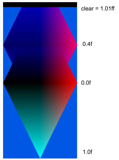
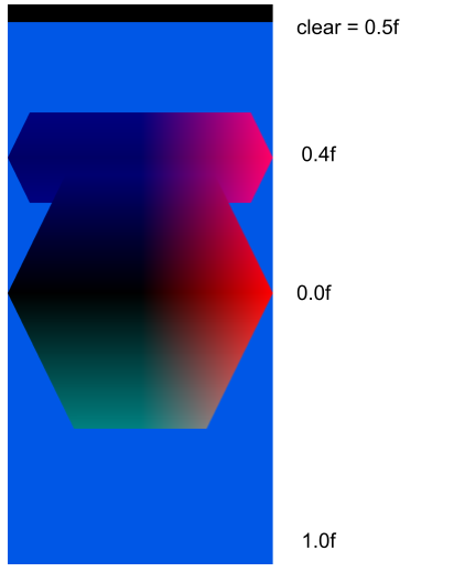
以下は縦軸と横軸のdepthが異なるひし形を2枚描いた図である。
上図が図形のすべてが描画されている状態。
下図は0.5fで初期化した場合で、depthの値が0.5fより大きいfragmentは描かれないことがわかる。
Input Assemble Stageの指定
Input Assembler Stage
Input Assembler Stageでの処理の記述について調べる。
graphics pipelineのstageの概要は以下に記載。
aqoole-hateena.hatenablog.com
Vertex Input State
レンダリングを行うためには、pipelineにデータを入力する必要がある。
データを入力する際に、どのbufferからデータを取ってくるのかを指定するために、vertex indexやinstance indexを使用できる。
VkPipelineVertexInputStateCreateInfo
shaderがデータを扱えるようにvertex inputの情報を記述する。
// Provided by VK_VERSION_1_0
typedef struct VkPipelineVertexInputStateCreateInfo {
    VkStructureType                             sType;
    const void*                                 pNext;
    VkPipelineVertexInputStateCreateFlags       flags;
    uint32_t                                    vertexBindingDescriptionCount;
    const VkVertexInputBindingDescription*      pVertexBindingDescriptions;
    uint32_t                                    vertexAttributeDescriptionCount;
    const VkVertexInputAttributeDescription*    pVertexAttributeDescriptions;
} VkPipelineVertexInputStateCreateInfo;
VertexInputAttributesとVertexInputBindings
VertexInputAttributes : Vertex shader variablesがbufferにどのように存在しているかを表す。variablesがvkbufferにboundされる際に、variablesとVertexInputAttributesのnumberが紐づく。
VertexInputBindings : vertex dataにbufferをbindする。VertexInputAttributesがVertexInputBindingsに紐づき、VertexInputBindingsはvkbufferに紐づく。
Vertex shaders can define input variables, which receive vertex attribute data transferred from one or more VkBuffer(s) by drawing commands. Vertex shader input variables are bound to buffers via an indirect binding where the vertex shader associates a vertex input attribute number with each variable, vertex input attributes are associated to vertex input bindings on a per-pipeline basis, and vertex input bindings are associated with specific buffers on a per-draw basis via the vkCmdBindVertexBuffers command.
Vulkan® 1.2.203 - A Specification (with all registered Vulkan extensions)
VkVertexInputAttributeDescription
vertex bufferにある各vertexに対して、vertex attributeがどこにあるのかを表す。
// Provided by VK_VERSION_1_0
typedef struct VkVertexInputAttributeDescription {
    uint32_t    location;
    uint32_t    binding;
    VkFormat    format;
    uint32_t    offset;
} VkVertexInputAttributeDescription;
- location is the shader input location number for this attribute.
- binding is the binding number which this attribute takes its data from.
- format is the size and type of the vertex attribute data.
- offset is a byte offset of this attribute relative to the start of an element in the vertex input binding.
location
vertex shader内で使われるindex。locationは連続である必要もなければ、すべてのlocationがパイプライン内で使用される必要もない。binding
どのbufferからbindされているのか、このattributeがどこからデータを取ってくるのかを表す。対応するVkVertexInputBindingDescriptionのbindingと一致する。VkVertexInputBindingDescription
bindしているbufferの詳細を表す。
// Provided by VK_VERSION_1_0
typedef struct VkVertexInputBindingDescription {
    uint32_t             binding;
    uint32_t             stride;
    VkVertexInputRate    inputRate;
} VkVertexInputBindingDescription;
- binding is the binding number that this structure describes.
- stride is the byte stride between consecutive elements within the buffer.
- inputRate is a VkVertexInputRate value specifying whether vertex attribute addressing is a function of the vertex index or of the instance index.
binding
bindのindexを表す。stride
bindされている情報がbufferの先頭からどの距離にあるかを示す(bytes)。inputRate
vertex attributesのデータがvertex indexかinstance indexであるかを指定する。VkPipelineInputAssemblyStateCreateInfo
Drawing can be achieved in two modes:
- Programmable Mesh Shading, the mesh shader assembles primitives, or
- Programmable Primitive Shading, the input primitives are assembled
as follows.
Each draw is made up of zero or more vertices and zero or more instances, which are processed by the device and result in the assembly of primitives. Primitives are assembled according to the pInputAssemblyState member of the VkGraphicsPipelineCreateInfo structure, which is of type VkPipelineInputAssemblyStateCreateInfo:
mesh shading :
Vulkan® 1.2.203 - A Specification (with all registered Vulkan extensions)
primitive shading :
Vulkan® 1.2.203 - A Specification (with all registered Vulkan extensions)
描画には大きく2つのアプローチがあり、
- mesh shading : 図形がmesh shaderでassembleされる(組み立てられる)。
- primitive shading : 頂点やinstanceをもとにassembleされる。
VkPipelineInputAssemblyStateCreateInfoは後者の方法で実行する。
// Provided by VK_VERSION_1_0
typedef struct VkPipelineInputAssemblyStateCreateInfo {
    VkStructureType                            sType;
    const void*                                pNext;
    VkPipelineInputAssemblyStateCreateFlags    flags;
    VkPrimitiveTopology                        topology;
    VkBool32                                   primitiveRestartEnable;
} VkPipelineInputAssemblyStateCreateInfo;
VkPipelineInputAssemblyStateCreateInfo(3)
topology
topology is a VkPrimitiveTopology defining the primitive topology
VkPrimitiveTopology
// Provided by VK_VERSION_1_0
typedef enum VkPrimitiveTopology {
    VK_PRIMITIVE_TOPOLOGY_POINT_LIST = 0,
    VK_PRIMITIVE_TOPOLOGY_LINE_LIST = 1,
    VK_PRIMITIVE_TOPOLOGY_LINE_STRIP = 2,
    VK_PRIMITIVE_TOPOLOGY_TRIANGLE_LIST = 3,
    VK_PRIMITIVE_TOPOLOGY_TRIANGLE_STRIP = 4,
    VK_PRIMITIVE_TOPOLOGY_TRIANGLE_FAN = 5,
    VK_PRIMITIVE_TOPOLOGY_LINE_LIST_WITH_ADJACENCY = 6,
    VK_PRIMITIVE_TOPOLOGY_LINE_STRIP_WITH_ADJACENCY = 7,
    VK_PRIMITIVE_TOPOLOGY_TRIANGLE_LIST_WITH_ADJACENCY = 8,
    VK_PRIMITIVE_TOPOLOGY_TRIANGLE_STRIP_WITH_ADJACENCY = 9,
    VK_PRIMITIVE_TOPOLOGY_PATCH_LIST = 10,
} VkPrimitiveTopology;
primitiveRestartEnable
primitiveRestartEnable controls whether a special vertex index value is treated as restarting the assembly of primitives. This enable only applies to indexed draws (vkCmdDrawIndexed, vkCmdDrawMultiIndexedEXT, and vkCmdDrawIndexedIndirect), and the special index value is either 0xFFFFFFFF when the indexType parameter of vkCmdBindIndexBuffer is equal to VK_INDEX_TYPE_UINT32, 0xFF when indexType is equal to VK_INDEX_TYPE_UINT8_EXT, or 0xFFFF when indexType is equal to VK_INDEX_TYPE_UINT16. Primitive restart is not allowed for “list” topologies, unless one of the features primitiveTopologyPatchListRestart (for VK_PRIMITIVE_TOPOLOGY_PATCH_LIST) or primitiveTopologyListRestart (for all other list topologies) is enabled.
特別なvertex indexで図形のassembleをrestartするかどうかを決める。topoligyがlist系のものでは有効にできない。
| Special Value | IndexType of vkCmdBindIndexBuffer |
|---|---|
| 0xFFFFFFFF | VK_INDEX_TYPE_UINT32 |
| 0xFFFF | VK_INDEX_TYPE_UINT16 |
| 0xFF | VK_INDEX_TYPE_UINT8_EXT |
更新履歴
2022/1/23 Vertex Input State 新規追加
Blending Stageの指定
Blending Stage
Blending Stageではcolor blendの指定を行う。
aqoole-hateena.hatenablog.com
color blendとは
Blending combines the incoming source fragment’s R, G, B, and A values with the destination R, G, B, and A values of each sample stored in the framebuffer at the fragment’s (xf,yf) location. Blending is performed for each color sample covered by the fragment, rather than just once for each fragment.
Vulkan® 1.2.203 - A Specification (with all registered Vulkan extensions)
color blendとは、source colorとdst colorのfragments(RGBA)を混ぜ合わせて、対応するframe bufferの位置(,
)に格納することである。
つまりsource color, dst colorの選び方と、色の混ぜ方を決めることが重要となる。
VkPipelineColorBlendStateCreateInfo
VkPipelineColorBlendStateCreateInfo - Structure specifying parameters of a newly created pipeline color blend state
// Provided by VK_VERSION_1_0
typedef struct VkPipelineColorBlendStateCreateInfo {
    VkStructureType                               sType;
    const void*                                   pNext;
    VkPipelineColorBlendStateCreateFlags          flags;
    VkBool32                                      logicOpEnable;
    VkLogicOp                                     logicOp;
    uint32_t                                      attachmentCount;
    const VkPipelineColorBlendAttachmentState*    pAttachments;
    float                                         blendConstants[4];
} VkPipelineColorBlendStateCreateInfo;
- flags is a bitmask of VkPipelineColorBlendStateCreateFlagBits specifying additional color blending information.
- logicOpEnable controls whether to apply Logical Operations.
- logicOp selects which logical operation to apply.
- attachmentCount is the number of VkPipelineColorBlendAttachmentState elements in pAttachments.
- pAttachments is a pointer to an array of VkPipelineColorBlendAttachmentState structures defining blend state for each color attachment.
- blendConstants is a pointer to an array of four values used as the R, G, B, and A components of the blend constant that are used in blending, depending on the blend factor.
flags
現状、設定できるパラメータは1種類だけのよう。
// Provided by VK_ARM_rasterization_order_attachment_access
typedef enum VkPipelineColorBlendStateCreateFlagBits {
  // Provided by VK_ARM_rasterization_order_attachment_access
    VK_PIPELINE_COLOR_BLEND_STATE_CREATE_RASTERIZATION_ORDER_ATTACHMENT_ACCESS_BIT_ARM = 0x00000001,
} VkPipelineColorBlendStateCreateFlagBits;
VK_PIPELINE_COLOR_BLEND_STATE_CREATE_RASTERIZATION_ORDER_ATTACHMENT_ACCESS_BIT_ARM indicates that access to color and input attachments will have implicit framebuffer-local memory dependencies, allowing applications to express custom blending operations in a fragment shader. See renderpass feedback loops for more information.
VkPipelineColorBlendStateCreateFlagBits(3)
内容が理解できないので、仕様書の拡張機能について書かれてある部分を見てみる。
VK_ARM_rasterization_order_attachment_access
Renderpasses, and specifically subpass self-dependencies enable much of the same functionality as the framebuffer fetch and pixel local storage extensions did for OpenGL ES. But certain techniques such as programmable blending are awkward or impractical to implement with these alone, in part because a self-dependency is required every time a fragment will read a value at a given sample coordinate.
This extension extends the mechanism of input attachments to allow access to framebuffer attachments when used as both input and color, or depth/stencil, attachments from one fragment to the next, in rasterization order, without explicit synchronization.
Vulkan® 1.2.203 - A Specification (with all registered Vulkan extensions)
「fragmentがsample coordinateを読み込む場合に、常に自己依存が要求されることもあり、programmable blendingのような技術をRenderpassesとspecifically subpass self-dependenciesだけで実装するのは、あまりよくない」とある。color blendingをprogrammableにするには、通常のrenderpassとsubpassだけでは足りないようだ。
そこでこの拡張機能では、input attachmentsとcolor or depth/stencial attachments)の両方が使用されている場合に、明示的なsynchroなしでinput attachmentがframebuffer attachmentにアクセスすることを可能にする、とある。
Feedback loops
If a subpass uses the same attachment as both an input attachment and either a color attachment or a depth/stencil attachment, writes via the color or depth/stencil attachment are not automatically made visible to reads via the input attachment, causing a feedback loop, except in any of the following conditions:
Vulkan® 1.2.203 - A Specification (with all registered Vulkan extensions)
subpassがinput attachmentとcolor or depth/stencial attachmentの両方を持つとき、color or depth/stencial attachmentからの書き込みは、input attachmentから自動的に読み込めるようにvisibleの状態にはならない、とある。そしてこれがfeedback loopを生み出すとある。
Rendering within a subpass containing a feedback loop creates a data race, except in the following cases:
- If the attachment is used as color and input attachment, and the pipeline performing the read was created with VK_PIPELINE_COLOR_BLEND_STATE_CREATE_RASTERIZATION_ORDER_ATTACHMENT_ACCESS_BIT_ARM included in the flags member of the pColorBlendState member of its VkGraphicsPipelineCreateInfo. This creates a framebuffer-local memory dependency for each fragment generated by draw commands using this pipeline with the following properties:
- The first synchronization scope includes the VK_PIPELINE_STAGE_COLOR_ATTACHMENT_OUTPUT_BIT pipeline stage executed by all previous fragments (as defined by primitive order) in the corresponding framebuffer regions including those generated by the same draw command.
- The second synchronization scope includes the VK_PIPELINE_STAGE_FRAGMENT_SHADER_BIT pipeline stage executed by the generated fragment.
- The first access scope includes all writes to color attachments.
- The second access scope includes all reads from input attachments.
feedback loopsをもつsubpassでのrenderingではdata race(データ競合)が発生してしまうが、拡張機能を設定しておけば回避できる。拡張を設定することにより、各fragmentについてlocal memory依存のframebufferを作成できる。sync scopeとaccess scopeは書かれてある通りである。
logicOpEnable
The application can enable a logical operation between the fragment’s color values and the existing value in the framebuffer attachment. This logical operation is applied prior to updating the framebuffer attachment. Logical operations are applied only for signed and unsigned integer and normalized integer framebuffers. Logical operations are not applied to floating-point or sRGB format color attachments.
Vulkan® 1.2.203 - A Specification (with all registered Vulkan extensions)
logical operationsとは、fragmentの色とframe bufferに保存されている色の論理演算のことである。この演算はframe buffer attachmentが更新されるよりも前に行われる。logical operationsは整数型(signed, unsigned)のframe bufferにのみ適用される。
logicOpEnableはこの論理演算を行うかどうかを設定する。
logicOp
// Provided by VK_VERSION_1_0
typedef enum VkLogicOp {
    VK_LOGIC_OP_CLEAR = 0,
    VK_LOGIC_OP_AND = 1,
    VK_LOGIC_OP_AND_REVERSE = 2,
    VK_LOGIC_OP_COPY = 3,
    VK_LOGIC_OP_AND_INVERTED = 4,
    VK_LOGIC_OP_NO_OP = 5,
    VK_LOGIC_OP_XOR = 6,
    VK_LOGIC_OP_OR = 7,
    VK_LOGIC_OP_NOR = 8,
    VK_LOGIC_OP_EQUIVALENT = 9,
    VK_LOGIC_OP_INVERT = 10,
    VK_LOGIC_OP_OR_REVERSE = 11,
    VK_LOGIC_OP_COPY_INVERTED = 12,
    VK_LOGIC_OP_OR_INVERTED = 13,
    VK_LOGIC_OP_NAND = 14,
    VK_LOGIC_OP_SET = 15,
} VkLogicOp;
| Mode | Operation |
|---|---|
| VK_LOGIC_OP_CLEAR | 0 |
| VK_LOGIC_OP_AND | s ∧ d |
| VK_LOGIC_OP_AND_REVERSE | s ∧ ¬ d |
| VK_LOGIC_OP_COPY | s |
| VK_LOGIC_OP_AND_INVERTED | ¬ s ∧ d |
| VK_LOGIC_OP_NO_OP | d |
| VK_LOGIC_OP_XOR | s ⊕ d |
| VK_LOGIC_OP_OR | s ∨ d |
| VK_LOGIC_OP_NOR | ¬ (s ∨ d) |
| VK_LOGIC_OP_EQUIVALENT | ¬ (s ⊕ d) |
| VK_LOGIC_OP_INVERT | ¬ d |
| VK_LOGIC_OP_OR_REVERSE | s ∨ ¬ d |
| VK_LOGIC_OP_COPY_INVERTED | ¬ s |
| VK_LOGIC_OP_OR_INVERTED | ¬ s ∨ d |
| VK_LOGIC_OP_NAND | ¬ (s ∧ d) |
| VK_LOGIC_OP_SET | all 1s |
- s is the fragment’s
,
,
or
component value for the fragment output corresponding to the color attachment being updated, and
- d is the color attachment’s R, G, B or A component value
Vulkan® 1.2.203 - A Specification (with all registered Vulkan extensions)
pAttachments
VkPipelineColorBlendAttachmentState - Structure specifying a pipeline color blend attachment state
// Provided by VK_VERSION_1_0
typedef struct VkPipelineColorBlendAttachmentState {
    VkBool32                 blendEnable;
    VkBlendFactor            srcColorBlendFactor;
    VkBlendFactor            dstColorBlendFactor;
    VkBlendOp                colorBlendOp;
    VkBlendFactor            srcAlphaBlendFactor;
    VkBlendFactor            dstAlphaBlendFactor;
    VkBlendOp                alphaBlendOp;
    VkColorComponentFlags    colorWriteMask;
} VkPipelineColorBlendAttachmentState;
- blendEnable controls whether blending is enabled for the corresponding color attachment. If blending is not enabled, the source fragment’s color for that attachment is passed through unmodified.
- srcColorBlendFactor selects which blend factor is used to determine the source factors (Sr,Sg,Sb).
- dstColorBlendFactor selects which blend factor is used to determine the destination factors (Dr,Dg,Db).
- colorBlendOp selects which blend operation is used to calculate the RGB values to write to the color attachment.
- srcAlphaBlendFactor selects which blend factor is used to determine the source factor Sa.
- dstAlphaBlendFactor selects which blend factor is used to determine the destination factor Da.
- alphaBlendOp selects which blend operation is use to calculate the alpha values to write to the color attachment.
- colorWriteMask is a bitmask of VkColorComponentFlagBits specifying which of the R, G, B, and/or A components are enabled for writing, as described for the Color Write Mask.
blendEnable
color blendingを実行するかどうかを決める。
srcColorBlendFactor
VkBlendFactor - Framebuffer blending factors
// Provided by VK_VERSION_1_0
typedef enum VkBlendFactor {
    VK_BLEND_FACTOR_ZERO = 0,
    VK_BLEND_FACTOR_ONE = 1,
    VK_BLEND_FACTOR_SRC_COLOR = 2,
    VK_BLEND_FACTOR_ONE_MINUS_SRC_COLOR = 3,
    VK_BLEND_FACTOR_DST_COLOR = 4,
    VK_BLEND_FACTOR_ONE_MINUS_DST_COLOR = 5,
    VK_BLEND_FACTOR_SRC_ALPHA = 6,
    VK_BLEND_FACTOR_ONE_MINUS_SRC_ALPHA = 7,
    VK_BLEND_FACTOR_DST_ALPHA = 8,
    VK_BLEND_FACTOR_ONE_MINUS_DST_ALPHA = 9,
    VK_BLEND_FACTOR_CONSTANT_COLOR = 10,
    VK_BLEND_FACTOR_ONE_MINUS_CONSTANT_COLOR = 11,
    VK_BLEND_FACTOR_CONSTANT_ALPHA = 12,
    VK_BLEND_FACTOR_ONE_MINUS_CONSTANT_ALPHA = 13,
    VK_BLEND_FACTOR_SRC_ALPHA_SATURATE = 14,
    VK_BLEND_FACTOR_SRC1_COLOR = 15,
    VK_BLEND_FACTOR_ONE_MINUS_SRC1_COLOR = 16,
    VK_BLEND_FACTOR_SRC1_ALPHA = 17,
    VK_BLEND_FACTOR_ONE_MINUS_SRC1_ALPHA = 18,
} VkBlendFactor;
| VkBlendFactor | RGB Blend Factors (Sr,Sg,Sb) or (Dr,Dg,Db) | Alpha Blend Factor (Sa or Da) |
|---|---|---|
| VK_BLEND_FACTOR_ZERO | (0,0,0) | 0 |
| VK_BLEND_FACTOR_ONE | (1,1,1) | 1 |
| VK_BLEND_FACTOR_SRC_COLOR | (Rs0,Gs0,Bs0) | As0 |
| VK_BLEND_FACTOR_ONE_MINUS_SRC_COLOR | (1-Rs0,1-Gs0,1-Bs0) | 1-As0 |
| VK_BLEND_FACTOR_DST_COLOR | (Rd,Gd,Bd) | Ad |
| VK_BLEND_FACTOR_ONE_MINUS_DST_COLOR | (1-Rd,1-Gd,1-Bd) | 1-Ad |
| VK_BLEND_FACTOR_SRC_ALPHA | (As0,As0,As0) | As0 |
| VK_BLEND_FACTOR_ONE_MINUS_SRC_ALPHA | (1-As0,1-As0,1-As0) | 1-As0 |
| VK_BLEND_FACTOR_DST_ALPHA | (Ad,Ad,Ad) | Ad |
| VK_BLEND_FACTOR_ONE_MINUS_DST_ALPHA | (1-Ad,1-Ad,1-Ad) | 1-Ad |
| VK_BLEND_FACTOR_CONSTANT_COLOR | (Rc,Gc,Bc) | Ac |
| VK_BLEND_FACTOR_ONE_MINUS_CONSTANT_COLOR | (1-Rc,1-Gc,1-Bc) | 1-Ac |
| VK_BLEND_FACTOR_CONSTANT_ALPHA | (Ac,Ac,Ac) | Ac |
| VK_BLEND_FACTOR_ONE_MINUS_CONSTANT_ALPHA | (1-Ac,1-Ac,1-Ac) | 1-Ac |
| VK_BLEND_FACTOR_SRC_ALPHA_SATURATE | (f,f,f); f = min(As0,1-Ad) | 1 |
| VK_BLEND_FACTOR_SRC1_COLOR | (Rs1,Gs1,Bs1) | As1 |
| VK_BLEND_FACTOR_ONE_MINUS_SRC1_COLOR | (1-Rs1,1-Gs1,1-Bs1) | 1-As1 |
| VK_BLEND_FACTOR_SRC1_ALPHA | (As1,As1,As1) | As1 |
| VK_BLEND_FACTOR_ONE_MINUS_SRC1_ALPHA | (1-As1,1-As1,1-As1) | 1-As1 |
and
and
represent the second source color R, G, B, and A components, used in dual source blending modes
and
represent the R, G, B, and A components of the destination color
and
represent the blend constant R, G, B, and A components
VkBlendFactor(3)
source colorとして何を指定するのかを入力する。
colorBlendOp
// Provided by VK_VERSION_1_0
typedef enum VkBlendOp {
    VK_BLEND_OP_ADD = 0,
    VK_BLEND_OP_SUBTRACT = 1,
    VK_BLEND_OP_REVERSE_SUBTRACT = 2,
    VK_BLEND_OP_MIN = 3,
    VK_BLEND_OP_MAX = 4,
} VkBlendOp;VK_EXT_blend_operation_advancedの拡張機能を指定すれば、さらに多くのオプションを選べるようになる。
VkBlendOp(3)
それぞれのblendOpによる計算は以下の通り。
| VkBlendOp | RGB Components | Alpha Component |
|---|---|---|
| VK_BLEND_OP_ADD | ||
| VK_BLEND_OP_SUBTRACT | ||
| VK_BLEND_OP_REVERSE_SUBTRACT | ||
| VK_BLEND_OP_MIN | ||
| VK_BLEND_OP_MAX |
出典 : Table 1. Basic Blend OperationsVkBlendOp(3)
: Source Blend Factor
: Destination Blend Facror
colorWriteMask
VkColorComponentFlagBits - Bitmask controlling which components are written to the framebuffer
Bits which can be set in VkPipelineColorBlendAttachmentState::colorWriteMask to determine whether the final color values R, G, B and A are written to the framebuffer attachment are:
// Provided by VK_VERSION_1_0
typedef enum VkColorComponentFlagBits {
    VK_COLOR_COMPONENT_R_BIT = 0x00000001,
    VK_COLOR_COMPONENT_G_BIT = 0x00000002,
    VK_COLOR_COMPONENT_B_BIT = 0x00000004,
    VK_COLOR_COMPONENT_A_BIT = 0x00000008,
} VkColorComponentFlagBits;
The color write mask operation is applied regardless of whether blending is enabled.
VkColorComponentFlagBits(3)
color maskはどの色が最終的にframe bufferに格納されるかを決める。color maskはblendEnableの値に依らず参照される。もしmaskが指定されていなければ、frame bufferの値は更新されない。
blendConstants
srcColorBlendFactorの欄であるように、constant colorの値を指定する。
サポートされているsample count取得方法
multisamplingの機能を利用する場合の、supported sample count取得具体例(Android)
VkImageFormatProperties imageFormatProp = {};
vkGetPhysicalDeviceImageFormatProperties(physicalDevice, VK_FORMAT_R8G8B8A8_UNORM,
    VK_IMAGE_TYPE_2D, VK_IMAGE_TILING_LINEAR, VK_IMAGE_USAGE_COLOR_ATTACHMENT_BIT,
    VK_NULL_HANDLE, &imageFormatProp);
__android_log_print(ANDROID_LOG_INFO, "limits sample count", "%s", std::to_string(imageFormatProp.sampleCounts).c_str());
pipelineでのmultisamplingの指定方法については以下記事参照。
aqoole-hateena.hatenablog.com
VkImageFormatProperties
// Provided by VK_VERSION_1_0
typedef struct VkImageFormatProperties {
    VkExtent3D            maxExtent;
    uint32_t              maxMipLevels;
    uint32_t              maxArrayLayers;
    VkSampleCountFlags    sampleCounts;
    VkDeviceSize          maxResourceSize;
} VkImageFormatProperties;
sampleCounts is a bitmask of VkSampleCountFlagBits specifying all the supported sample counts for this image as described below.
VkImageFormatProperties(3)
sampleCountsにサポートされるsample countが格納されるのだが、bitmaskの形で情報が取得される。
VkSampleCountFlagBits
// Provided by VK_VERSION_1_0
typedef enum VkSampleCountFlagBits {
    VK_SAMPLE_COUNT_1_BIT = 0x00000001,
    VK_SAMPLE_COUNT_2_BIT = 0x00000002,
    VK_SAMPLE_COUNT_4_BIT = 0x00000004,
    VK_SAMPLE_COUNT_8_BIT = 0x00000008,
    VK_SAMPLE_COUNT_16_BIT = 0x00000010,
    VK_SAMPLE_COUNT_32_BIT = 0x00000020,
    VK_SAMPLE_COUNT_64_BIT = 0x00000040,
} VkSampleCountFlagBits;
vkGetPhysicalDeviceImageFormatProperties()
vkGetPhysicalDeviceImageFormatProperties - Lists physical device's image format capabilities
To query additional capabilities specific to image types, call:
// Provided by VK_VERSION_1_0
VkResult vkGetPhysicalDeviceImageFormatProperties(
    VkPhysicalDevice                            physicalDevice,
    VkFormat                                    format,
    VkImageType                                 type,
    VkImageTiling                               tiling,
    VkImageUsageFlags                           usage,
    VkImageCreateFlags                          flags,
    VkImageFormatProperties*                    pImageFormatProperties);
pImageFormatProperties is a pointer to a VkImageFormatProperties structure in which capabilities are returned.
vkGetPhysicalDeviceImageFormatProperties(3)
サポートされている情報の取得はvkGetPhysicalDeviceImageFormatProperties()関数で行う。
Rasterization Stageの指定
Rasterization Stageでの処理
rasterization stageではrasterizationとmultisamplingの処理が行われる。
それぞれVkPipelineRasterizationStateCreateInfoとVkPipelineMultisampleStateCreateInfoにパラメータを記述する。
VkPipelineRasterizationStateCreateInfo
// Provided by VK_VERSION_1_0
typedef struct VkPipelineRasterizationStateCreateInfo {
    VkStructureType                            sType;
    const void*                                pNext;
    VkPipelineRasterizationStateCreateFlags    flags;
    VkBool32                                   depthClampEnable;
    VkBool32                                   rasterizerDiscardEnable;
    VkPolygonMode                              polygonMode;
    VkCullModeFlags                            cullMode;
    VkFrontFace                                frontFace;
    VkBool32                                   depthBiasEnable;
    float                                      depthBiasConstantFactor;
    float                                      depthBiasClamp;
    float                                      depthBiasSlopeFactor;
    float                                      lineWidth;
} VkPipelineRasterizationStateCreateInfo;
- depthClampEnable controls whether to clamp the fragment’s depth values as described in Depth Test. If the pipeline is not created with VkPipelineRasterizationDepthClipStateCreateInfoEXT present then enabling depth clamp will also disable clipping primitives to the z planes of the frustrum as described in Primitive Clipping. Otherwise depth clipping is controlled by the state set in VkPipelineRasterizationDepthClipStateCreateInfoEXT.
- rasterizerDiscardEnable controls whether primitives are discarded immediately before the rasterization stage.
- polygonMode is the triangle rendering mode. See VkPolygonMode.
- cullMode is the triangle facing direction used for primitive culling. See VkCullModeFlagBits.
- frontFace is a VkFrontFace value specifying the front-facing triangle orientation to be used for culling.
- depthBiasEnable controls whether to bias fragment depth values.
depthClampEnable
depth testとは、あるdepth valueがpositionに対応するdepth bufferの値と比較し、よりfrontであれば表示し、behindであれば表示しない、というもの。depth test自体はrenderingでは一般的な用語なので、OpenGLでの説明を引用。
When depth testing is enabled, OpenGL tests the depth value of a fragment against the content of the depth buffer. OpenGL performs a depth test and if this test passes, the fragment is rendered and the depth buffer is updated with the new depth value. If the depth test fails, the fragment is discarded.
LearnOpenGL - Depth testing
depthClampEnableはdepthの値をdepth testの値にclampするかどうかを決める。
cullMode
破棄する三角形の向きを決める。
cullは「淘汰、間引き」の意味。
cullingの意味・使い方・読み方 | Weblio英和辞書
VkCullModeFlagBits
VkCullModeFlagBits - Bitmask controlling triangle culling
// Provided by VK_VERSION_1_0
typedef enum VkCullModeFlagBits {
    VK_CULL_MODE_NONE = 0,
    VK_CULL_MODE_FRONT_BIT = 0x00000001,
    VK_CULL_MODE_BACK_BIT = 0x00000002,
    VK_CULL_MODE_FRONT_AND_BACK = 0x00000003,
} VkCullModeFlagBits;
- VK_CULL_MODE_NONE specifies that no triangles are discarded
- VK_CULL_MODE_FRONT_BIT specifies that front-facing triangles are discarded
- VK_CULL_MODE_BACK_BIT specifies that back-facing triangles are discarded
- VK_CULL_MODE_FRONT_AND_BACK specifies that all triangles are discarded.
Following culling, fragments are produced for any triangles which have not been discarded.
VkCullModeFlagBits(3)
frontFace
どの回り方(反時計回りor時計回り)が表面かを指定する。
// Provided by VK_VERSION_1_0
typedef enum VkFrontFace {
    VK_FRONT_FACE_COUNTER_CLOCKWISE = 0,
    VK_FRONT_FACE_CLOCKWISE = 1,
} VkFrontFace;
depthBiasEnable
depth biasとは
The depth values of all fragments generated by the rasterization of a polygon can be biased (offset) by a single depth bias value o that is computed for that polygon.
Vulkan® 1.2.203 - A Specification (with all registered Vulkan extensions)
すべてのdepth valueはひとつのdepth bias valueでbias可能とある。
biasは「偏り」の意味。
biasの意味・使い方・読み方 | Weblio英和辞書
これだけだと意味が分からないのでもう少し調べてみると、Nvidiaのdeveloper zoneにはこのようにある。
Specify the constant offset used to compute a depth offset for polygons. See the units parameter description on the OpenGL glPolygonOffset manual page for details. See the D3DRS_DEPTHBIAS render state description for DirectX 9.
DepthBias
depth offsetを計算するための定数のoffsetとある。
詳細を知りたければOpenGL glPolygonOffset manual pageを見ろとあるので、見てみた。
glPolygonOffset
void glPolygonOffset(GLfloat factor,
 	GLfloat units);
glPolygonOffset is useful for rendering hidden-line images, for applying decals to surfaces, and for rendering solids with highlighted edges.
Description
When GL_POLYGON_OFFSET_FILL, GL_POLYGON_OFFSET_LINE, or GL_POLYGON_OFFSET_POINT is enabled, each fragment's depth value will be offset after it is interpolated from the depth values of the appropriate vertices. The value of the offset is factor × DZ + r × units , where DZ is a measurement of the change in depth relative to the screen area of the polygon, and r is the smallest value that is guaranteed to produce a resolvable offset for a given implementation. The offset is added before the depth test is performed and before the value is written into the depth buffer.
glPolygonOffset - OpenGL 4 Reference Pages
「depth bias(glPolygonOffset)は隠れたラインやimagesをsurface上に転写するときに使える」とある。壁の奥にオブジェクトがある場合に、そのedge部分だけを壁の表面に描きたい場合などに、depthにoffsetを与えて補正することにより描けるよう。
VkPipelineMultisampleStateCreateInfo
// Provided by VK_VERSION_1_0
typedef struct VkPipelineMultisampleStateCreateInfo {
    VkStructureType                          sType;
    const void*                              pNext;
    VkPipelineMultisampleStateCreateFlags    flags;
    VkSampleCountFlagBits                    rasterizationSamples;
    VkBool32                                 sampleShadingEnable;
    float                                    minSampleShading;
    const VkSampleMask*                      pSampleMask;
    VkBool32                                 alphaToCoverageEnable;
    VkBool32                                 alphaToOneEnable;
} VkPipelineMultisampleStateCreateInfo;
- rasterizationSamples is a VkSampleCountFlagBits value specifying the number of samples used in rasterization.
- sampleShadingEnable can be used to enable Sample Shading.
- minSampleShading specifies a minimum fraction of sample shading if sampleShadingEnable is set to VK_TRUE.
- pSampleMask is a pointer to an array of VkSampleMask values used in the sample mask test.
- alphaToCoverageEnable controls whether a temporary coverage value is generated based on the alpha component of the fragment’s first color output as specified in the Multisample Coverage section.
- alphaToOneEnable controls whether the alpha component of the fragment’s first color output is replaced with one as described in Multisample Coverage.
rasterizationSamplesではsampleのカウントを指定する。
VkPhysicalDeviceLimitsのstandardSampleLocationsがVK_TRUEの場合、下tableのようなsample locationsになる。
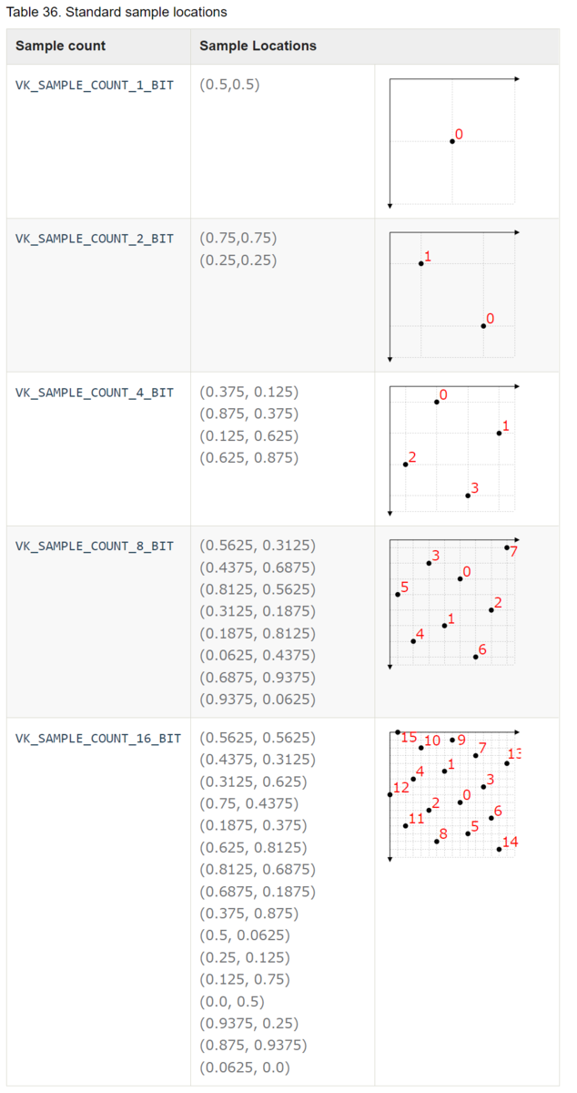
出典:Vulkan® 1.2.203 - A Specification (with all registered Vulkan extensions)
sampleShadingEnableはsample rate shadingの機能のon/offを設定する。
sample rate shadingとは、fragment shaderがpixelごとではなく、sampleごとに動作することである。
multisamplingにより図形のedgeはよりきれいに表現されるが、samplingした結果をfragment shaderに送るため、multisamplingはfragment shaderが高空間周波数の結果を出力した場合に対しては無力である。空間周波数とは、空間内の位置全体で周期的な構造の特性である。
Spatial frequency - Wikipedia
sampleShadingEnableをonにするとfragment shaderがsample rateで動くため、このような場合にも対応できる。
minSampleShadingはsampleShadingEnableが有効な場合のパラメータで、0.0f - 1.0fの値を入力する。
minSampleShadingはfragment shaderの動作頻度を管理する。
値が1.0の場合、pixel内のすべてのsampleにおいてfragment shaderが実行され、その結果を別のsampleにも送る。
値が0.0から1.0の間の場合、fragment shaderを実行するsample数の割合はdevice依存で計算される。
pSampleMaskは32bitのbit maskである。sample indexとbit位置が対応しており、bitが1であれば、fragment shaderが実行される。
If sample shading is enabled, fragment shaders will only see values of 1 for samples being shaded - other bits will be 0.
Vulkan® 1.2.203 - A Specification (with all registered Vulkan extensions)
alphaToCoverageEnableは対応する位置のfragment shaderの出力のalpha値に基づいて、一時的なcoverage maskを決めるかどうかを定める。
coverage maskとはmultisamplingにおいて、実際に有効となるfragment shaderをもつsampleのindexに対応したbit maskである。
If alphaToCoverageEnable is enabled, a temporary coverage mask is generated where each bit is determined by the fragment’s alpha value, which is ANDed with the fragment coverage mask.
Vulkan® 1.2.203 - A Specification (with all registered Vulkan extensions)
alphaToOneEnableはalpha値を1.0fなどの最大値に書き換えるかどうかを決める。
Finally, if alphaToOneEnable is enabled, each alpha value is replaced by the maximum representable alpha value for fixed-point color attachments, or by 1.0 for floating-point attachments. Otherwise, the alpha values are not changed.
Vulkan® 1.2.203 - A Specification (with all registered Vulkan extensions)
サポートされているsample count取得方法
更新履歴
2022/1/17 サポートされているsample count取得方法を追記
Vertex Post-processing Stageの指定
Vertex Post-processing Stage
記事にあるGraphics pipeline diagramのVertex Post-processing stageでは、いわゆるClip and Cullの処理が行われる。
aqoole-hateena.hatenablog.com
Clip and Cullとはworld座標から画面に表示される範囲を抽出することである。
座標変換
Vertex Post-processing StageではClip SpaceからScreen Spaceへの変換を行う。Clip SpaceはNormal Device Coordinatesともよばれ、Screen SpaceはWindow Coordinatesともよばれる。
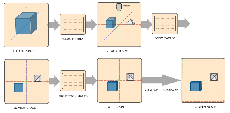
出典:LearnOpenGL - Coordinate Systems
※図はOpenGLのもののため、y軸の向きが逆向きになっている。
Vertex Post-processingの処理はVkPipelineViewportStateCreateInfoに記述する。
VkPipelineViewportStateCreateInfo
VkPipelineViewportStateCreateInfo - Structure specifying parameters of a newly created pipeline viewport state
// Provided by VK_VERSION_1_0
typedef struct VkPipelineViewportStateCreateInfo {
    VkStructureType                       sType;
    const void*                           pNext;
    VkPipelineViewportStateCreateFlags    flags;
    uint32_t                              viewportCount;
    const VkViewport*                     pViewports;
    uint32_t                              scissorCount;
    const VkRect2D*                       pScissors;
} VkPipelineViewportStateCreateInfo;
- pViewports is a pointer to an array of VkViewport structures, defining the viewport transforms. If the viewport state is dynamic, this member is ignored.
- pScissors is a pointer to an array of VkRect2D structures defining the rectangular bounds of the scissor for the corresponding viewport. If the scissor state is dynamic, this member is ignored.
VkViewportとVkRect2Dの情報が必要。VkViewportは座標変換の内のviewport transformsに必要で、VkRect2Dはviewportの領域の境界を指定するのに必要。
VkViewport
VkViewport - Structure specifying a viewport
// Provided by VK_VERSION_1_0
typedef struct VkViewport {
    float    x;
    float    y;
    float    width;
    float    height;
    float    minDepth;
    float    maxDepth;
} VkViewport;
- x and y are the viewport’s upper left corner (x,y).
- width and height are the viewport’s width and height, respectively.
- minDepth and maxDepth are the depth range for the viewport.
window coordinatesは通常、左上を(0, 0)とし、pixelの数だけwidthとheightをもつ座標系である。
swapchainで作成しているwindow全体をviewportとする場合の具体例
  VkViewport viewports{
      .x = 0,
      .y = 0,
      .width = (float)displaySize.width,
      .height = (float)displaySize.height,
      .minDepth = 0.0f,
      .maxDepth = 1.0f,
  };
VkRect2D
VkRect2D - Structure specifying a two-dimensional subregion.
Rectangles are used to describe a specified rectangular region of pixels within an image or framebuffer.
// Provided by VK_VERSION_1_0
typedef struct VkRect2D {
    VkOffset2D    offset;
    VkExtent2D    extent;
} VkRect2D;
- offset is a VkOffset2D specifying the rectangle offset.
- extent is a VkExtent2D specifying the rectangle extent.
offsetとextentをそれぞれ構造体で定義する。
VkOffset2D
// Provided by VK_VERSION_1_0
typedef struct VkOffset2D {
    int32_t    x;
    int32_t    y;
} VkOffset2D;
- x is the x offset.
- y is the y offset.
VkExtent2D
// Provided by VK_VERSION_1_0
typedef struct VkExtent2D {
    uint32_t    width;
    uint32_t    height;
} VkExtent2D;
- width is the width of the extent.
- height is the height of the extent.
extentとは「広さ、範囲」の意味。
extentの意味・使い方・読み方 | Weblio英和辞書
Shader Stageの指定
Shader Stageの指定
pipeline diagramにあるように、pipelineにはshaderを使用することにより処理を行うpipeline shader stageがある。
aqoole-hateena.hatenablog.com
pipeline shader stageを指定するには、VkPipelineShaderStageCreateInfoを実装するshader stageの数だけ記述する。
最終的にVkGraphicsPipelineCreateInfoに情報を記述することで、pipelineを作成することができる。
VkPipelineShaderStageCreateInfo
VkPipelineShaderStageCreateInfo - Structure specifying parameters of a newly created pipeline shader stage
// Provided by VK_VERSION_1_0
typedef struct VkPipelineShaderStageCreateInfo {
    VkStructureType                     sType;
    const void*                         pNext;
    VkPipelineShaderStageCreateFlags    flags;
    VkShaderStageFlagBits               stage;
    VkShaderModule                      module;
    const char*                         pName;
    const VkSpecializationInfo*         pSpecializationInfo;
} VkPipelineShaderStageCreateInfo;
- sType is the type of this structure.
- pNext is NULL or a pointer to a structure extending this structure.
- flags is a bitmask of VkPipelineShaderStageCreateFlagBits specifying how the pipeline shader stage will be generated.
- stage is a VkShaderStageFlagBits value specifying a single pipeline stage.
- module is a VkShaderModule object containing the shader for this stage.
- pName is a pointer to a null-terminated UTF-8 string specifying the entry point name of the shader for this stage.
- pSpecializationInfo is a pointer to a VkSpecializationInfo structure, as described in Specialization Constants, or NULL.
VkShaderStageFlagBits
VkShaderStageFlagBits - Bitmask specifying a pipeline stage
// Provided by VK_VERSION_1_0
typedef enum VkShaderStageFlagBits {
    VK_SHADER_STAGE_VERTEX_BIT = 0x00000001,
    VK_SHADER_STAGE_TESSELLATION_CONTROL_BIT = 0x00000002,
    VK_SHADER_STAGE_TESSELLATION_EVALUATION_BIT = 0x00000004,
    VK_SHADER_STAGE_GEOMETRY_BIT = 0x00000008,
    VK_SHADER_STAGE_FRAGMENT_BIT = 0x00000010,
    VK_SHADER_STAGE_COMPUTE_BIT = 0x00000020,
    VK_SHADER_STAGE_ALL_GRAPHICS = 0x0000001F,
    VK_SHADER_STAGE_ALL = 0x7FFFFFFF,
:
}VkShaderStageFlagBits;
- VK_SHADER_STAGE_VERTEX_BIT specifies the vertex stage.
- VK_SHADER_STAGE_TESSELLATION_CONTROL_BIT specifies the tessellation control stage.
- VK_SHADER_STAGE_TESSELLATION_EVALUATION_BIT specifies the tessellation evaluation stage.
- VK_SHADER_STAGE_GEOMETRY_BIT specifies the geometry stage.
- VK_SHADER_STAGE_FRAGMENT_BIT specifies the fragment stage.
- VK_SHADER_STAGE_COMPUTE_BIT specifies the compute stage.
- VK_SHADER_STAGE_ALL_GRAPHICS is a combination of bits used as shorthand to specify all graphics stages defined above (excluding the compute stage).
- VK_SHADER_STAGE_ALL is a combination of bits used as shorthand to specify all shader stages supported by the device, including all additional stages which are introduced by extensions.
Ray tracingやVK_NV_などの拡張期機能は割愛している。
Rasterizationのpipelineで指定できるshader stageの種類は、基本的にはここに定義されている5種類しかない。(COMPUTE_BITを除く)