サポートされているsample count取得方法
multisamplingの機能を利用する場合の、supported sample count取得具体例(Android)
VkImageFormatProperties imageFormatProp = {};
vkGetPhysicalDeviceImageFormatProperties(physicalDevice, VK_FORMAT_R8G8B8A8_UNORM,
    VK_IMAGE_TYPE_2D, VK_IMAGE_TILING_LINEAR, VK_IMAGE_USAGE_COLOR_ATTACHMENT_BIT,
    VK_NULL_HANDLE, &imageFormatProp);
__android_log_print(ANDROID_LOG_INFO, "limits sample count", "%s", std::to_string(imageFormatProp.sampleCounts).c_str());
pipelineでのmultisamplingの指定方法については以下記事参照。
aqoole-hateena.hatenablog.com
VkImageFormatProperties
// Provided by VK_VERSION_1_0
typedef struct VkImageFormatProperties {
    VkExtent3D            maxExtent;
    uint32_t              maxMipLevels;
    uint32_t              maxArrayLayers;
    VkSampleCountFlags    sampleCounts;
    VkDeviceSize          maxResourceSize;
} VkImageFormatProperties;
sampleCounts is a bitmask of VkSampleCountFlagBits specifying all the supported sample counts for this image as described below.
VkImageFormatProperties(3)
sampleCountsにサポートされるsample countが格納されるのだが、bitmaskの形で情報が取得される。
VkSampleCountFlagBits
// Provided by VK_VERSION_1_0
typedef enum VkSampleCountFlagBits {
    VK_SAMPLE_COUNT_1_BIT = 0x00000001,
    VK_SAMPLE_COUNT_2_BIT = 0x00000002,
    VK_SAMPLE_COUNT_4_BIT = 0x00000004,
    VK_SAMPLE_COUNT_8_BIT = 0x00000008,
    VK_SAMPLE_COUNT_16_BIT = 0x00000010,
    VK_SAMPLE_COUNT_32_BIT = 0x00000020,
    VK_SAMPLE_COUNT_64_BIT = 0x00000040,
} VkSampleCountFlagBits;
vkGetPhysicalDeviceImageFormatProperties()
vkGetPhysicalDeviceImageFormatProperties - Lists physical device's image format capabilities
To query additional capabilities specific to image types, call:
// Provided by VK_VERSION_1_0
VkResult vkGetPhysicalDeviceImageFormatProperties(
    VkPhysicalDevice                            physicalDevice,
    VkFormat                                    format,
    VkImageType                                 type,
    VkImageTiling                               tiling,
    VkImageUsageFlags                           usage,
    VkImageCreateFlags                          flags,
    VkImageFormatProperties*                    pImageFormatProperties);
pImageFormatProperties is a pointer to a VkImageFormatProperties structure in which capabilities are returned.
vkGetPhysicalDeviceImageFormatProperties(3)
サポートされている情報の取得はvkGetPhysicalDeviceImageFormatProperties()関数で行う。
Rasterization Stageの指定
Rasterization Stageでの処理
rasterization stageではrasterizationとmultisamplingの処理が行われる。
それぞれVkPipelineRasterizationStateCreateInfoとVkPipelineMultisampleStateCreateInfoにパラメータを記述する。
VkPipelineRasterizationStateCreateInfo
// Provided by VK_VERSION_1_0
typedef struct VkPipelineRasterizationStateCreateInfo {
    VkStructureType                            sType;
    const void*                                pNext;
    VkPipelineRasterizationStateCreateFlags    flags;
    VkBool32                                   depthClampEnable;
    VkBool32                                   rasterizerDiscardEnable;
    VkPolygonMode                              polygonMode;
    VkCullModeFlags                            cullMode;
    VkFrontFace                                frontFace;
    VkBool32                                   depthBiasEnable;
    float                                      depthBiasConstantFactor;
    float                                      depthBiasClamp;
    float                                      depthBiasSlopeFactor;
    float                                      lineWidth;
} VkPipelineRasterizationStateCreateInfo;
- depthClampEnable controls whether to clamp the fragment’s depth values as described in Depth Test. If the pipeline is not created with VkPipelineRasterizationDepthClipStateCreateInfoEXT present then enabling depth clamp will also disable clipping primitives to the z planes of the frustrum as described in Primitive Clipping. Otherwise depth clipping is controlled by the state set in VkPipelineRasterizationDepthClipStateCreateInfoEXT.
- rasterizerDiscardEnable controls whether primitives are discarded immediately before the rasterization stage.
- polygonMode is the triangle rendering mode. See VkPolygonMode.
- cullMode is the triangle facing direction used for primitive culling. See VkCullModeFlagBits.
- frontFace is a VkFrontFace value specifying the front-facing triangle orientation to be used for culling.
- depthBiasEnable controls whether to bias fragment depth values.
depthClampEnable
depth testとは、あるdepth valueがpositionに対応するdepth bufferの値と比較し、よりfrontであれば表示し、behindであれば表示しない、というもの。depth test自体はrenderingでは一般的な用語なので、OpenGLでの説明を引用。
When depth testing is enabled, OpenGL tests the depth value of a fragment against the content of the depth buffer. OpenGL performs a depth test and if this test passes, the fragment is rendered and the depth buffer is updated with the new depth value. If the depth test fails, the fragment is discarded.
LearnOpenGL - Depth testing
depthClampEnableはdepthの値をdepth testの値にclampするかどうかを決める。
cullMode
破棄する三角形の向きを決める。
cullは「淘汰、間引き」の意味。
cullingの意味・使い方・読み方 | Weblio英和辞書
VkCullModeFlagBits
VkCullModeFlagBits - Bitmask controlling triangle culling
// Provided by VK_VERSION_1_0
typedef enum VkCullModeFlagBits {
    VK_CULL_MODE_NONE = 0,
    VK_CULL_MODE_FRONT_BIT = 0x00000001,
    VK_CULL_MODE_BACK_BIT = 0x00000002,
    VK_CULL_MODE_FRONT_AND_BACK = 0x00000003,
} VkCullModeFlagBits;
- VK_CULL_MODE_NONE specifies that no triangles are discarded
- VK_CULL_MODE_FRONT_BIT specifies that front-facing triangles are discarded
- VK_CULL_MODE_BACK_BIT specifies that back-facing triangles are discarded
- VK_CULL_MODE_FRONT_AND_BACK specifies that all triangles are discarded.
Following culling, fragments are produced for any triangles which have not been discarded.
VkCullModeFlagBits(3)
frontFace
どの回り方(反時計回りor時計回り)が表面かを指定する。
// Provided by VK_VERSION_1_0
typedef enum VkFrontFace {
    VK_FRONT_FACE_COUNTER_CLOCKWISE = 0,
    VK_FRONT_FACE_CLOCKWISE = 1,
} VkFrontFace;
depthBiasEnable
depth biasとは
The depth values of all fragments generated by the rasterization of a polygon can be biased (offset) by a single depth bias value o that is computed for that polygon.
Vulkan® 1.2.203 - A Specification (with all registered Vulkan extensions)
すべてのdepth valueはひとつのdepth bias valueでbias可能とある。
biasは「偏り」の意味。
biasの意味・使い方・読み方 | Weblio英和辞書
これだけだと意味が分からないのでもう少し調べてみると、Nvidiaのdeveloper zoneにはこのようにある。
Specify the constant offset used to compute a depth offset for polygons. See the units parameter description on the OpenGL glPolygonOffset manual page for details. See the D3DRS_DEPTHBIAS render state description for DirectX 9.
DepthBias
depth offsetを計算するための定数のoffsetとある。
詳細を知りたければOpenGL glPolygonOffset manual pageを見ろとあるので、見てみた。
glPolygonOffset
void glPolygonOffset(GLfloat factor,
 	GLfloat units);
glPolygonOffset is useful for rendering hidden-line images, for applying decals to surfaces, and for rendering solids with highlighted edges.
Description
When GL_POLYGON_OFFSET_FILL, GL_POLYGON_OFFSET_LINE, or GL_POLYGON_OFFSET_POINT is enabled, each fragment's depth value will be offset after it is interpolated from the depth values of the appropriate vertices. The value of the offset is factor × DZ + r × units , where DZ is a measurement of the change in depth relative to the screen area of the polygon, and r is the smallest value that is guaranteed to produce a resolvable offset for a given implementation. The offset is added before the depth test is performed and before the value is written into the depth buffer.
glPolygonOffset - OpenGL 4 Reference Pages
「depth bias(glPolygonOffset)は隠れたラインやimagesをsurface上に転写するときに使える」とある。壁の奥にオブジェクトがある場合に、そのedge部分だけを壁の表面に描きたい場合などに、depthにoffsetを与えて補正することにより描けるよう。
VkPipelineMultisampleStateCreateInfo
// Provided by VK_VERSION_1_0
typedef struct VkPipelineMultisampleStateCreateInfo {
    VkStructureType                          sType;
    const void*                              pNext;
    VkPipelineMultisampleStateCreateFlags    flags;
    VkSampleCountFlagBits                    rasterizationSamples;
    VkBool32                                 sampleShadingEnable;
    float                                    minSampleShading;
    const VkSampleMask*                      pSampleMask;
    VkBool32                                 alphaToCoverageEnable;
    VkBool32                                 alphaToOneEnable;
} VkPipelineMultisampleStateCreateInfo;
- rasterizationSamples is a VkSampleCountFlagBits value specifying the number of samples used in rasterization.
- sampleShadingEnable can be used to enable Sample Shading.
- minSampleShading specifies a minimum fraction of sample shading if sampleShadingEnable is set to VK_TRUE.
- pSampleMask is a pointer to an array of VkSampleMask values used in the sample mask test.
- alphaToCoverageEnable controls whether a temporary coverage value is generated based on the alpha component of the fragment’s first color output as specified in the Multisample Coverage section.
- alphaToOneEnable controls whether the alpha component of the fragment’s first color output is replaced with one as described in Multisample Coverage.
rasterizationSamplesではsampleのカウントを指定する。
VkPhysicalDeviceLimitsのstandardSampleLocationsがVK_TRUEの場合、下tableのようなsample locationsになる。
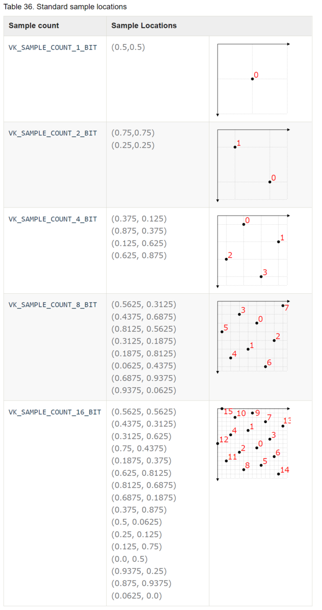
出典:Vulkan® 1.2.203 - A Specification (with all registered Vulkan extensions)
sampleShadingEnableはsample rate shadingの機能のon/offを設定する。
sample rate shadingとは、fragment shaderがpixelごとではなく、sampleごとに動作することである。
multisamplingにより図形のedgeはよりきれいに表現されるが、samplingした結果をfragment shaderに送るため、multisamplingはfragment shaderが高空間周波数の結果を出力した場合に対しては無力である。空間周波数とは、空間内の位置全体で周期的な構造の特性である。
Spatial frequency - Wikipedia
sampleShadingEnableをonにするとfragment shaderがsample rateで動くため、このような場合にも対応できる。
minSampleShadingはsampleShadingEnableが有効な場合のパラメータで、0.0f - 1.0fの値を入力する。
minSampleShadingはfragment shaderの動作頻度を管理する。
値が1.0の場合、pixel内のすべてのsampleにおいてfragment shaderが実行され、その結果を別のsampleにも送る。
値が0.0から1.0の間の場合、fragment shaderを実行するsample数の割合はdevice依存で計算される。
pSampleMaskは32bitのbit maskである。sample indexとbit位置が対応しており、bitが1であれば、fragment shaderが実行される。
If sample shading is enabled, fragment shaders will only see values of 1 for samples being shaded - other bits will be 0.
Vulkan® 1.2.203 - A Specification (with all registered Vulkan extensions)
alphaToCoverageEnableは対応する位置のfragment shaderの出力のalpha値に基づいて、一時的なcoverage maskを決めるかどうかを定める。
coverage maskとはmultisamplingにおいて、実際に有効となるfragment shaderをもつsampleのindexに対応したbit maskである。
If alphaToCoverageEnable is enabled, a temporary coverage mask is generated where each bit is determined by the fragment’s alpha value, which is ANDed with the fragment coverage mask.
Vulkan® 1.2.203 - A Specification (with all registered Vulkan extensions)
alphaToOneEnableはalpha値を1.0fなどの最大値に書き換えるかどうかを決める。
Finally, if alphaToOneEnable is enabled, each alpha value is replaced by the maximum representable alpha value for fixed-point color attachments, or by 1.0 for floating-point attachments. Otherwise, the alpha values are not changed.
Vulkan® 1.2.203 - A Specification (with all registered Vulkan extensions)
サポートされているsample count取得方法
更新履歴
2022/1/17 サポートされているsample count取得方法を追記
Vertex Post-processing Stageの指定
Vertex Post-processing Stage
記事にあるGraphics pipeline diagramのVertex Post-processing stageでは、いわゆるClip and Cullの処理が行われる。
aqoole-hateena.hatenablog.com
Clip and Cullとはworld座標から画面に表示される範囲を抽出することである。
座標変換
Vertex Post-processing StageではClip SpaceからScreen Spaceへの変換を行う。Clip SpaceはNormal Device Coordinatesともよばれ、Screen SpaceはWindow Coordinatesともよばれる。
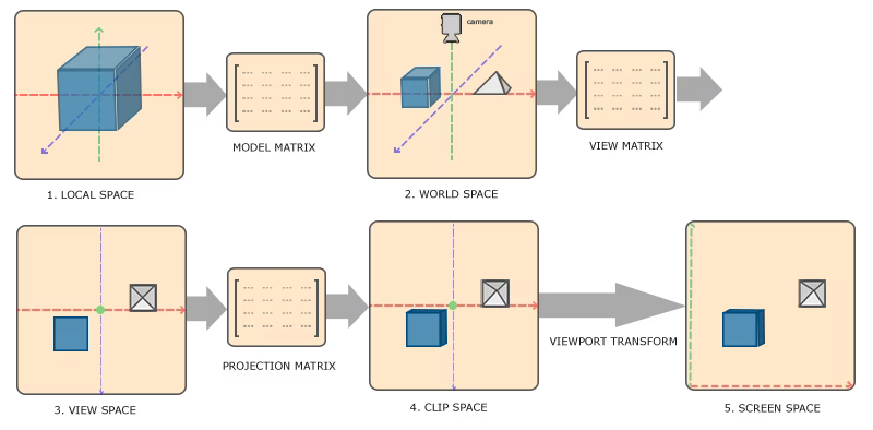
出典:LearnOpenGL - Coordinate Systems
※図はOpenGLのもののため、y軸の向きが逆向きになっている。
Vertex Post-processingの処理はVkPipelineViewportStateCreateInfoに記述する。
VkPipelineViewportStateCreateInfo
VkPipelineViewportStateCreateInfo - Structure specifying parameters of a newly created pipeline viewport state
// Provided by VK_VERSION_1_0
typedef struct VkPipelineViewportStateCreateInfo {
    VkStructureType                       sType;
    const void*                           pNext;
    VkPipelineViewportStateCreateFlags    flags;
    uint32_t                              viewportCount;
    const VkViewport*                     pViewports;
    uint32_t                              scissorCount;
    const VkRect2D*                       pScissors;
} VkPipelineViewportStateCreateInfo;
- pViewports is a pointer to an array of VkViewport structures, defining the viewport transforms. If the viewport state is dynamic, this member is ignored.
- pScissors is a pointer to an array of VkRect2D structures defining the rectangular bounds of the scissor for the corresponding viewport. If the scissor state is dynamic, this member is ignored.
VkViewportとVkRect2Dの情報が必要。VkViewportは座標変換の内のviewport transformsに必要で、VkRect2Dはviewportの領域の境界を指定するのに必要。
VkViewport
VkViewport - Structure specifying a viewport
// Provided by VK_VERSION_1_0
typedef struct VkViewport {
    float    x;
    float    y;
    float    width;
    float    height;
    float    minDepth;
    float    maxDepth;
} VkViewport;
- x and y are the viewport’s upper left corner (x,y).
- width and height are the viewport’s width and height, respectively.
- minDepth and maxDepth are the depth range for the viewport.
window coordinatesは通常、左上を(0, 0)とし、pixelの数だけwidthとheightをもつ座標系である。
swapchainで作成しているwindow全体をviewportとする場合の具体例
  VkViewport viewports{
      .x = 0,
      .y = 0,
      .width = (float)displaySize.width,
      .height = (float)displaySize.height,
      .minDepth = 0.0f,
      .maxDepth = 1.0f,
  };
VkRect2D
VkRect2D - Structure specifying a two-dimensional subregion.
Rectangles are used to describe a specified rectangular region of pixels within an image or framebuffer.
// Provided by VK_VERSION_1_0
typedef struct VkRect2D {
    VkOffset2D    offset;
    VkExtent2D    extent;
} VkRect2D;
- offset is a VkOffset2D specifying the rectangle offset.
- extent is a VkExtent2D specifying the rectangle extent.
offsetとextentをそれぞれ構造体で定義する。
VkOffset2D
// Provided by VK_VERSION_1_0
typedef struct VkOffset2D {
    int32_t    x;
    int32_t    y;
} VkOffset2D;
- x is the x offset.
- y is the y offset.
VkExtent2D
// Provided by VK_VERSION_1_0
typedef struct VkExtent2D {
    uint32_t    width;
    uint32_t    height;
} VkExtent2D;
- width is the width of the extent.
- height is the height of the extent.
extentとは「広さ、範囲」の意味。
extentの意味・使い方・読み方 | Weblio英和辞書
Shader Stageの指定
Shader Stageの指定
pipeline diagramにあるように、pipelineにはshaderを使用することにより処理を行うpipeline shader stageがある。
aqoole-hateena.hatenablog.com
pipeline shader stageを指定するには、VkPipelineShaderStageCreateInfoを実装するshader stageの数だけ記述する。
最終的にVkGraphicsPipelineCreateInfoに情報を記述することで、pipelineを作成することができる。
VkPipelineShaderStageCreateInfo
VkPipelineShaderStageCreateInfo - Structure specifying parameters of a newly created pipeline shader stage
// Provided by VK_VERSION_1_0
typedef struct VkPipelineShaderStageCreateInfo {
    VkStructureType                     sType;
    const void*                         pNext;
    VkPipelineShaderStageCreateFlags    flags;
    VkShaderStageFlagBits               stage;
    VkShaderModule                      module;
    const char*                         pName;
    const VkSpecializationInfo*         pSpecializationInfo;
} VkPipelineShaderStageCreateInfo;
- sType is the type of this structure.
- pNext is NULL or a pointer to a structure extending this structure.
- flags is a bitmask of VkPipelineShaderStageCreateFlagBits specifying how the pipeline shader stage will be generated.
- stage is a VkShaderStageFlagBits value specifying a single pipeline stage.
- module is a VkShaderModule object containing the shader for this stage.
- pName is a pointer to a null-terminated UTF-8 string specifying the entry point name of the shader for this stage.
- pSpecializationInfo is a pointer to a VkSpecializationInfo structure, as described in Specialization Constants, or NULL.
VkShaderStageFlagBits
VkShaderStageFlagBits - Bitmask specifying a pipeline stage
// Provided by VK_VERSION_1_0
typedef enum VkShaderStageFlagBits {
    VK_SHADER_STAGE_VERTEX_BIT = 0x00000001,
    VK_SHADER_STAGE_TESSELLATION_CONTROL_BIT = 0x00000002,
    VK_SHADER_STAGE_TESSELLATION_EVALUATION_BIT = 0x00000004,
    VK_SHADER_STAGE_GEOMETRY_BIT = 0x00000008,
    VK_SHADER_STAGE_FRAGMENT_BIT = 0x00000010,
    VK_SHADER_STAGE_COMPUTE_BIT = 0x00000020,
    VK_SHADER_STAGE_ALL_GRAPHICS = 0x0000001F,
    VK_SHADER_STAGE_ALL = 0x7FFFFFFF,
:
}VkShaderStageFlagBits;
- VK_SHADER_STAGE_VERTEX_BIT specifies the vertex stage.
- VK_SHADER_STAGE_TESSELLATION_CONTROL_BIT specifies the tessellation control stage.
- VK_SHADER_STAGE_TESSELLATION_EVALUATION_BIT specifies the tessellation evaluation stage.
- VK_SHADER_STAGE_GEOMETRY_BIT specifies the geometry stage.
- VK_SHADER_STAGE_FRAGMENT_BIT specifies the fragment stage.
- VK_SHADER_STAGE_COMPUTE_BIT specifies the compute stage.
- VK_SHADER_STAGE_ALL_GRAPHICS is a combination of bits used as shorthand to specify all graphics stages defined above (excluding the compute stage).
- VK_SHADER_STAGE_ALL is a combination of bits used as shorthand to specify all shader stages supported by the device, including all additional stages which are introduced by extensions.
Ray tracingやVK_NV_などの拡張期機能は割愛している。
Rasterizationのpipelineで指定できるshader stageの種類は、基本的にはここに定義されている5種類しかない。(COMPUTE_BITを除く)
Graphics Pipeline基礎知識
Graphics pipelineとは
コマンドの入力によって、データが各ステージで処理される生産ラインのこと。
各ステージは実装によってon/offが可能だが、vertex shaderのステージだけは例外なく実装する必要がある。
Block diagram of the Vulkan pipeline
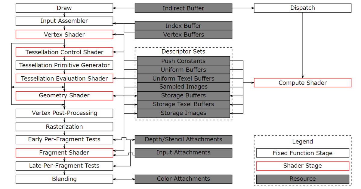
出典:Vulkan® 1.2.203 - A Specification
Figure 2. Block diagram of the Vulkan pipeline
左がpipelineのフローである。
調べた用語をまとめる。
Tessellation Control Shader
tessellation要素のためのプログラム可能なshader stage.
tessellationとは3頂点などで表されるポリゴンをさらに細かく分割して、より詳細かつ滑らかに表現する技法である。
テッセレーション - Wikipedia
tessellationはVulkanではオプションの操作で、tessellation control shaderとtessellation evaluation shaderの両方がpipelineに含まれる場合に行うことができる。
Vulkan® 1.2.203 - A Specification
Geometry Shader
wikipediaには以下のように説明されている。
ジオメトリシェーダーにより、実行時に頂点数を増減させたり、プリミティブの種類を変更したりすることが可能となる。OpenGLではプリミティブシェーダーとも呼ばれる。
シェーダー - Wikipedia
例えば三角形のメッシュをワイヤーフレームの三角形に変形させることなどが行える。
Vertex Post-Processing
Clip and cullの操作などがここに含まれる。Clip and cullとは描画される範囲を決めることである。
描画されない範囲は捨てて、描画される範囲をrasterizeするために次のステージに送る。
Rasterization
頂点の羅列で表されている図形を将来的にpixelで表現するために、fragment shaderに渡せるようなfragmentsに変換する。
fragmentsとは、図形が載っているpixelのことである。
Vulkanの仕様書には、以下のように説明されている。
Rasterization is the process by which a primitive is converted to a two-dimensional image. Each discrete location of this image contains associated data such as depth, color, or other attributes.
Vulkan® 1.2.203 - A Specification
「Rasterizationとは図形を2次元のimageに変換することで、imageにはdepthやcolorなどの情報が含まれる。」とある。
各pipeline stageの記述方法について
別記事にまとめていく。
shader stages
input assemble
Raterization
Vertex Post-processing
Blending
更新履歴
2022/1/22 Rasterization 表現を微修正
Bufferの作成とメモリ割り当てについて
vkCreateBuffer()
vkCreateBuffer - Create a new buffer object
// Provided by VK_VERSION_1_0
VkResult vkCreateBuffer(
    VkDevice                                    device,
    const VkBufferCreateInfo*                   pCreateInfo,
    const VkAllocationCallbacks*                pAllocator,
    VkBuffer*                                   pBuffer);
vkCreateBuffer(3)
Bufferの作成にはvkCreateBuffer()を使用する。
作成に当たり、VkBufferCreateInfoを埋める必要がある。
VkBufferCreateInfo
VkBufferCreateInfo - Structure specifying the parameters of a newly created buffer object
// Provided by VK_VERSION_1_0
typedef struct VkBufferCreateInfo {
    VkStructureType        sType;
    const void*            pNext;
    VkBufferCreateFlags    flags;
    VkDeviceSize           size;
    VkBufferUsageFlags     usage;
    VkSharingMode          sharingMode;
    uint32_t               queueFamilyIndexCount;
    const uint32_t*        pQueueFamilyIndices;
} VkBufferCreateInfo;
- sType is the type of this structure.
- pNext is NULL or a pointer to a structure extending this structure.
- flags is a bitmask of VkBufferCreateFlagBits specifying additional parameters of the buffer.
- size is the size in bytes of the buffer to be created.
- usage is a bitmask of VkBufferUsageFlagBits specifying allowed usages of the buffer.
- sharingMode is a VkSharingMode value specifying the sharing mode of the buffer when it will be accessed by multiple queue families.
- queueFamilyIndexCount is the number of entries in the pQueueFamilyIndices array.
- pQueueFamilyIndices is a pointer to an array of queue families that will access this buffer. It is ignored if sharingMode is not VK_SHARING_MODE_CONCURRENT.
VkSharingMode
VkSharingMode - Buffer and image sharing modes.
Buffer and image objects are created with a sharing mode controlling how they can be accessed from queues.
Sharing ModeとはQueueからのaccess modeのこと。
// Provided by VK_VERSION_1_0
typedef enum VkSharingMode {
    VK_SHARING_MODE_EXCLUSIVE = 0,
    VK_SHARING_MODE_CONCURRENT = 1,
} VkSharingMode;
メンバはEXCLUSIVEとCONCURRENTの2つのみ。
- VK_SHARING_MODE_EXCLUSIVE specifies that access to any range or image subresource of the object will be exclusive to a single queue family at a time.
- VK_SHARING_MODE_CONCURRENT specifies that concurrent access to any range or image subresource of the object from multiple queue families is supported.
exclusiveは「排他的な、他を入れない」という意味で、concurrentは「同時」という意味。
exclusive とは 意味・読み方・表現 | Weblio英和辞書
concurrent とは 意味・読み方・表現 | Weblio英和辞書
VK_SHARING_MODE_EXCLUSIVE を指定すると、一度にひとつのqueue familyからしかアクセスできず、VK_SHARING_MODE_CONCURRENT を指定すると一度に複数のqueue familyからアクセスできる。
vkAllocateMemory()
vkAllocateMemory - Allocate device memory
作成したBufferをデバイスメモリに割り当てるには、vkAllocateMemory()を使用する。
// Provided by VK_VERSION_1_0
VkResult vkAllocateMemory(
    VkDevice                                    device,
    const VkMemoryAllocateInfo*                 pAllocateInfo,
    const VkAllocationCallbacks*                pAllocator,
    VkDeviceMemory*                             pMemory);
- device is the logical device that owns the memory.
- pAllocateInfo is a pointer to a VkMemoryAllocateInfo structure describing parameters of the allocation. A successfully returned allocation must use the requested parameters — no substitution is permitted by the implementation.
- pAllocator controls host memory allocation as described in the Memory Allocation chapter.
- pMemory is a pointer to a VkDeviceMemory handle in which information about the allocated memory is returned.
VkMemoryAllocateInfoによる具体的なパラメータの指定が必要。
VkMemoryAllocateInfo
VkMemoryAllocateInfo - Structure containing parameters of a memory allocation
// Provided by VK_VERSION_1_0
typedef struct VkMemoryAllocateInfo {
    VkStructureType    sType;
    const void*        pNext;
    VkDeviceSize       allocationSize;
    uint32_t           memoryTypeIndex;
} VkMemoryAllocateInfo;
- sType is the type of this structure.
- pNext is NULL or a pointer to a structure extending this structure.
- allocationSize is the size of the allocation in bytes.
- memoryTypeIndex is an index identifying a memory type from the memoryTypes array of the VkPhysicalDeviceMemoryProperties structure.
使用したいmemory typeを、VkPhysicalDeviceMemoryPropertiesのmemoryTypes[]のindexで指定する必要がある。
VkPhysicalDeviceMemoryProperties
VkPhysicalDeviceMemoryProperties - Structure specifying physical device memory properties
// Provided by VK_VERSION_1_0
typedef struct VkPhysicalDeviceMemoryProperties {
    uint32_t        memoryTypeCount;
    VkMemoryType    memoryTypes[VK_MAX_MEMORY_TYPES];
    uint32_t        memoryHeapCount;
    VkMemoryHeap    memoryHeaps[VK_MAX_MEMORY_HEAPS];
} VkPhysicalDeviceMemoryProperties;
VkPhysicalDeviceMemoryProperties(3)
vkGetBufferMemoryRequirements()でphysical deviceでサポートされているVkPhysicalDeviceMemoryPropertiesが取得できるので、そこから使用するmemory typesのindexを指定してVkMemoryAllocateInfoに記述する。
vkAllocateMemory()の具体例
サンプルコードでよく見かける具体例。
VkMemoryRequirements memReq;
vkGetBufferMemoryRequirements(device, buffer, &memReq);
VkMemoryAllocateInfo allocInfo{
    .sType = VK_STRUCTURE_TYPE_MEMORY_ALLOCATE_INFO,
    .pNext = nullptr,
    .allocationSize = memReq.size,
    .memoryTypeIndex = 0,  // Memory type assigned in the next step
};
vkGetBufferMemoryRequirements()でbuffer objectのmemory requiementを取得する。
vkGetBufferMemoryRequirements(3)
このrequirementでallocInfo.allocationSizeの値を埋める。
VkMemoryRequirements
VkMemoryRequirements - Structure specifying memory requirements
// Provided by VK_VERSION_1_0
typedef struct VkMemoryRequirements {
    VkDeviceSize    size;
    VkDeviceSize    alignment;
    uint32_t        memoryTypeBits;
} VkMemoryRequirements;
- size is the size, in bytes, of the memory allocation required for the resource.
- alignment is the alignment, in bytes, of the offset within the allocation required for the resource.
- memoryTypeBits is a bitmask and contains one bit set for every supported memory type for the resource. Bit i is set if and only if the memory type i in the VkPhysicalDeviceMemoryProperties structure for the physical device is supported for the resource.
memoryTypeBitsはphysical deviceでサポートされているビットセットを表す。bitのi番目はVkPhysicalDeviceMemoryProperties.memoryTypesのi番目に対応する。
この事実をもとに、割り当てるメモリで使いたいmemory propertyをもつmemoryTypesは何番目かを調べる。
uint32_t SearchIndex(typeBits, requirements_mask){
  for (uint32_t i = 0; i < memReq.memoryTypeCount; i++) {
    if ((typeBits & 1) == 1) {
      // Type is available, does it match user properties?
      if ((memoryProperties.memoryTypes[i].propertyFlags & requirements_mask) ==
          requirements_mask) {
        return i;
      }
    }
    typeBits >>= 1;
  }
  throw std::runtime_error("failed to find suitable memory types for buffer");
}
typeBitsにはVkMemoryRequirements.memoryTypeBitsを入れ、requirements_maskには指定したいVkFlags(VK_MEMORY_PROPERTY_HOST_VISIBLE_BIT | VK_MEMORY_PROPERTY_HOST_COHERENT_BITなど)を入れる。
i番目のindexがi番目のtypeBitsのbitに対応しているので、bitが一致するかどうかを確かめる。一致していた場合、使用したいrequirements_maskがmemoryProperties.memoryTypesのi番目であるかどうかを確かめる。一致していた場合、このiが欲しいiなので、returnしてiを受け取る。一致しない場合、typeBitsを一つ右にシフトして、次のiに対応させてからsearchのループをやり直す。
以上の手順により、requirements_maskに対応するmemoryProperties.memoryTypesのindexを取得できる。
これでVkMemoryAllocateInfoが完成する。
ImageViewの作成について
vkCreateImageView
ImageViewはvkCreateImageView()で作成できるが、作成にはVkImageViewCreateInfo構造体に必要な情報をインプットする必要がある。
vkCreateImageView(3)
VkImageViewCreateInfo
VkImageViewCreateInfo - Structure specifying parameters of a newly created image view
// Provided by VK_VERSION_1_0
typedef struct VkImageViewCreateInfo {
    VkStructureType            sType;
    const void*                pNext;
    VkImageViewCreateFlags     flags;
    VkImage                    image;
    VkImageViewType            viewType;
    VkFormat                   format;
    VkComponentMapping         components;
    VkImageSubresourceRange    subresourceRange;
} VkImageViewCreateInfo;
- components is a VkComponentMapping structure specifying a remapping of color components (or of depth or stencil components after they have been converted into color components).
componentsについて、説明文にremappingとあるのでimageのRGBAの並びを変更することができる。
VkComponentMapping
VkComponentMapping - Structure specifying a color component mapping
// Provided by VK_VERSION_1_0
typedef struct VkComponentMapping {
    VkComponentSwizzle    r;
    VkComponentSwizzle    g;
    VkComponentSwizzle    b;
    VkComponentSwizzle    a;
} VkComponentMapping;
VkComponentMapping(3)
構造体をたらい回しにされているが、VkComponentSwizzleのメンバにて要素を指定する。
VkComponentSwizzle
VkComponentSwizzle - Specify how a component is swizzled
// Provided by VK_VERSION_1_0
typedef enum VkComponentSwizzle {
    VK_COMPONENT_SWIZZLE_IDENTITY = 0,
    VK_COMPONENT_SWIZZLE_ZERO = 1,
    VK_COMPONENT_SWIZZLE_ONE = 2,
    VK_COMPONENT_SWIZZLE_R = 3,
    VK_COMPONENT_SWIZZLE_G = 4,
    VK_COMPONENT_SWIZZLE_B = 5,
    VK_COMPONENT_SWIZZLE_A = 6,
} VkComponentSwizzle;
VkComponentSwizzle(3)
swizzleについて、weblioで意味を調べると
To permute bits, or elements of a vector.
ビットまたはベクトルの要素を並べ替えます。
ということなので、RGBA要素の入れ替えについてのパラメータ。
また、VK_COMPONENT_SWIZZLE_IDENTITYは同じ位置のパラメータを指定する。つまり 各ComponentにVK_COMPONENT_SWIZZLE_IDENTITYを指定した場合、以下の値が指定される。
| Component | Identity Mapping |
|---|---|
| components.r | VK_COMPONENT_SWIZZLE_R |
| components.g | VK_COMPONENT_SWIZZLE_G |
| components.b | VK_COMPONENT_SWIZZLE_B |
| components.a | VK_COMPONENT_SWIZZLE_A |